
Tap drill size chart: metric, fine, UNC/UNF and G threads — the right drill diameter before tapping
Tap drill diameters for M1.6–M30, UNC/UNF and G (BSP) threads; how percent thread affects torque and strength; why forming taps need a larger hole.
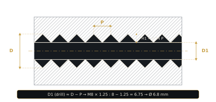
The most common cause of tap breakage is not the tap but the hole. A hole drilled 0.2 mm undersize noticeably raises the volume of material the tap must remove and the torque it must carry; even an HSS-E tap will break. This note collects the chart every shop looks up daily and explains the logic behind it.
Rule of thumb: drill diameter ≈ thread diameter − pitch
For metric threads the practical rule for the tap drill is:
D1 ≈ D − P (D: nominal thread diameter, P: pitch)
For M8 × 1.25: 8 − 1.25 = 6.75 → Ø 6.8 mm drill. For M10 × 1.5: 10 − 1.5 = 8.5 mm. With a standard 6H tolerance this gives about 75 % thread height and matches the DIN 336 tables.
Metric coarse (M) — DIN 13
| Thread | Pitch (mm) | Drill Ø (mm) |
|---|---|---|
| M1.6 | 0.35 | 1.25 |
| M2 | 0.40 | 1.60 |
| M2.5 | 0.45 | 2.05 |
| M3 | 0.50 | 2.50 |
| M4 | 0.70 | 3.30 |
| M5 | 0.80 | 4.20 |
| M6 | 1.00 | 5.00 |
| M8 | 1.25 | 6.80 |
| M10 | 1.50 | 8.50 |
| M12 | 1.75 | 10.20 |
| M14 | 2.00 | 12.00 |
| M16 | 2.00 | 14.00 |
| M18 | 2.50 | 15.50 |
| M20 | 2.50 | 17.50 |
| M22 | 2.50 | 19.50 |
| M24 | 3.00 | 21.00 |
| M27 | 3.00 | 24.00 |
| M30 | 3.50 | 26.50 |
Metric fine (MF)
| Thread | Drill Ø (mm) |
|---|---|
| M8 × 1 | 7.00 |
| M10 × 1.25 | 8.80 |
| M10 × 1 | 9.00 |
| M12 × 1.5 | 10.50 |
| M12 × 1.25 | 10.80 |
| M14 × 1.5 | 12.50 |
| M16 × 1.5 | 14.50 |
| M18 × 1.5 | 16.50 |
| M20 × 1.5 | 18.50 |
| M24 × 2 | 22.00 |
| M30 × 2 | 28.00 |
UNC / UNF (inch)
| Thread | Drill (inch) | Drill Ø (mm) |
|---|---|---|
| 1/4-20 UNC | #7 | 5.10 |
| 5/16-18 UNC | F | 6.50 |
| 3/8-16 UNC | 5/16 | 7.90 |
| 7/16-14 UNC | U | 9.35 |
| 1/2-13 UNC | 27/64 | 10.70 |
| 5/8-11 UNC | 17/32 | 13.50 |
| 3/4-10 UNC | 21/32 | 16.70 |
| 1/4-28 UNF | #3 | 5.40 |
| 5/16-24 UNF | I | 6.90 |
| 3/8-24 UNF | Q | 8.40 |
| 1/2-20 UNF | 29/64 | 11.50 |
| 5/8-18 UNF | 37/64 | 14.70 |
G (BSP) pipe thread — parallel
| Thread | TPI | Drill Ø (mm) |
|---|---|---|
| G 1/8 | 28 | 8.80 |
| G 1/4 | 19 | 11.80 |
| G 3/8 | 19 | 15.30 |
| G 1/2 | 14 | 19.00 |
| G 3/4 | 14 | 24.50 |
| G 1 | 11 | 30.75 |
The G values are DIN 336 recommended drills; some charts give the minor diameter instead (e.g. 18.6 mm for G 1/2) and both conventions are in use. For tapered pipe threads such as NPT and NPTF the hole depends on thread depth and taper; use the tap manufacturer's own chart. Critical sealing threads must be gauged.
Percent thread: aim for 60–75 %, not 100 %
Many operators drill small because "a full thread is stronger". The opposite is true:
- Going from 75 % to 100 % thread height raises the tensile strength of the thread by only about 5 %.
- The same change raises tapping torque 2–3 times. That is where breakage, wear and torn threads come from.
- Steel and stainless: 65–75 %. Aluminium and ductile materials: 60–70 %. Cast iron may go to 75–80 %.
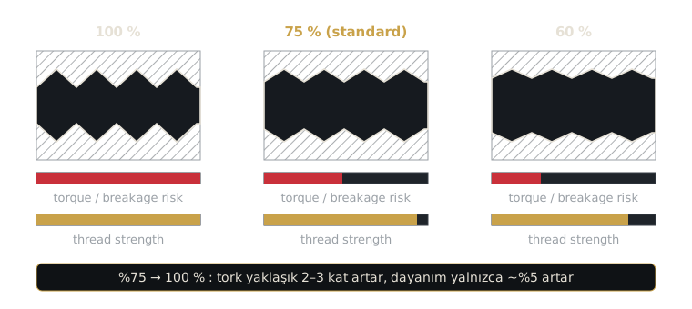
The chart values target exactly this band. A smaller hole does the tap no favour.
Forming (fluteless) taps: drill the hole larger
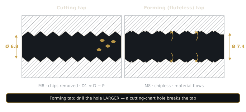
A forming tap removes no chips; it flows the material plastically into the thread profile. Because the crest is built from displaced material, the hole is drilled larger than for a cutting tap:
| Thread | Cutting tap Ø | Forming tap Ø |
|---|---|---|
| M3 | 2.50 | 2.80 |
| M4 | 3.30 | 3.70 |
| M5 | 4.20 | 4.60 |
| M6 | 5.00 | 5.50 |
| M8 | 6.80 | 7.40 |
| M10 | 8.50 | 9.30 |
| M12 | 10.20 | 11.10 |
Using a forming tap in a hole drilled to the cutting chart almost guarantees breakage. Forming taps are only for ductile materials (aluminium, copper alloys, low-carbon steel, austenitic stainless) with elongation above about 8 %; never in cast iron. Forming-tap drill sizes vary by about ±0.1 mm between manufacturers and target thread height; the tap maker's chart governs.
Three cases outside the chart
- Plated threads: if a bolt must fit after zinc or phosphate plating, use a 6G-tolerance tap and one drill size up.
- Blind-hole depth: hole depth = thread depth + tap chamfer length + chip room. With a spiral-flute tap leave at least 2–3 pitches of clearance.
- Drill wear: a worn drill cuts undersize. If tap breakage increases, measure the drill diameter with a micrometer first.
Quick checklist
- Drill size taken from the chart and checked with D − P.
- Cutting or forming? Forming uses the larger chart.
- Depth allowance left in blind holes.
- 6G chosen where the thread is plated afterwards.
- Critical threads verified with a go / no-go gauge.
Chart values are reference values consistent with DIN 336 and common manufacturer catalogues; for special tolerances use the manufacturer's table. Steel Wing supplies MCI Tool machine taps from stock in HSS-E and HSS-E-PM, spiral-flute, spiral-point and forming types; let us select the right size and type for your application together.